Multi-phase flows
A multi-phase flow concatenates several single-phase flows end-to-end, with switching times between phases and optional jump functions applied at each switch. Each phase is integrated on its own, and its final value (after the jump) becomes the initial condition of the next.
Concatenation operator *
Use the * operator to chain two flows at a switching time:
# flow1 on [t0, 1.0], then flow2 on [1.0, tf]
mpf = flow1 * (1.0, flow2)
MultiPhaseStateFlow
├─ phases: 2
├─ systems: VectorFieldSystem, VectorFieldSystem
├─ integrators: SciML, SciML
├─ switching_times: [1.0]
└─ jumps: Any[nothing]The result is a MultiPhaseStateFlow. You can chain more phases:
mpf3 = flow1 * (0.5, flow2) * (1.0, flow3)
MultiPhase.n_phases(mpf3)3Switching times must be strictly increasing. If they are not, a PreconditionError is thrown.
Phases with different dynamics
Each phase may wrap a different vector field — the dynamics, system type, and integrator are all free per phase. The only requirement is that all phases share the same TimeDependence and VariableDependence traits (both autonomous or both non-autonomous, both fixed or both variable).
# flow1: f(x) = -x   |   flow_het: f(x) = -2x  — different functions, same TD/VD
mpf_het = flow1 * (1.0, flow_het)
MultiPhase.n_phases(mpf_het)2This enables the typical use cases of multi-phase optimal control:
Bang-bang trajectories:
flow_plus * (t_switch, flow_minus)with distinct controlled dynamics per arc.Multi-regime systems: phases with different physical models (e.g. free flight / contact phase).
Different solvers per phase: stiff phases can use an implicit integrator while smooth phases use an explicit one.
Mixing state flows with Hamiltonian flows is not allowed — attempting it raises a PreconditionError.
Jumps at switching times
An additive vector jump_x is added to the state at the switching time (x ← x + jump_x). Pass it as the second element of the switching tuple:
jump_x = [0.5, 0.0]   # add 0.5 to the first component at the switch

mpf_jump = flow1 * (1.0, jump_x, flow2)
MultiPhaseStateFlow
├─ phases: 2
├─ systems: VectorFieldSystem, VectorFieldSystem
├─ integrators: SciML, SciML
├─ switching_times: [1.0]
└─ jumps: Any[[0.5, 0.0]]Pass nothing (or use the two-element tuple) for a continuous switch with no jump.
Function jumps
The second element may also be a callable instead of an additive vector:
State flow — f(x) must return the new state:
mpf_fn = flow1 * (1.0, x -> 2.0 .* x, flow2) # x ← 2x at t = 1.0MultiPhaseStateFlow
├─ phases: 2
├─ systems: VectorFieldSystem, VectorFieldSystem
├─ integrators: SciML, SciML
├─ switching_times: [1.0]
└─ jumps: Any[Main.var"#2#3"()]Hamiltonian flow — 3-element — f(x, p) returns (x', p'):
hmpf_fn = hflow1 * (
    1.0, (x, p) -> (2.0 .* x, p .+ 0.5), hflow2
)
MultiPhaseHamiltonianFlow
├─ phases: 2
├─ systems: HamiltonianVectorFieldSystem, HamiltonianVectorFieldSystem
├─ integrators: SciML, SciML
├─ switching_times: [1.0]
└─ jumps: Any[Main.var"#5#6"()]Hamiltonian flow — 4-element — each component independently accepts a vector, a callable, or nothing (identity). This allows state-only jumps without passing explicit zeros for the costate:
# state-only additive jump (costate unchanged)
hmpf_sx = hflow1 * (1.0, [0.1, 0.0], nothing, hflow2)

# callable on state, costate unchanged
hmpf_fx = hflow1 * (1.0, x -> 2.0 .* x, nothing, hflow2)
MultiPhaseHamiltonianFlow
├─ phases: 2
├─ systems: HamiltonianVectorFieldSystem, HamiltonianVectorFieldSystem
├─ integrators: SciML, SciML
├─ switching_times: [1.0]
└─ jumps: Any[(Main.var"#8#9"(), nothing)]Calling a multi-phase flow
Multi-phase flows share the same call interface as single-phase flows:
x0 = [1.0, 0.0]

# Point integration: final state only
xf = mpf(0.0, x0, 2.0)
2-element Vector{Float64}:
0.1353352833485776
0.0# Trajectory integration: full time history (phases merged)
sol = mpf((0.0, 2.0), x0)VectorFieldTrajectory
├─ result: PiecewiseIntegrationResult
├─ tspan: (0.0, 2.0)
├─ time points: 250
├─ switching times: [1.0]
└─ final state: [0.1353352833485776, 0.0]Inspecting a multi-phase flow
MultiPhase.n_phases(mpf)                 # number of phases
MultiPhase.get_flow(mpf, 1)              # flow for phase 1
MultiPhase.get_switching_time(mpf, 1)    # switching time after phase 1
MultiPhase.get_jump(mpf, 1) # jump at that switching time (nothing here)MultiPhase.get_flows(mpf) # tuple of all phase flows
MultiPhase.get_switching_times(mpf) # all switching times
MultiPhase.get_jumps(mpf) # all jump functionsPhase labels
Each flow can be given a label at construction, naming the phase it integrates (an arc bang, singular, boundary, …). Concatenation keeps the flows, so it keeps their labels, in order:
fa = Flows.Flow(vf; reltol=1e-8, label="decay")
fb = Flows.Flow(Data.VectorField(f_dyn2); reltol=1e-8, label="fast decay")
mpf_lab = fa * (1.0, fb)
MultiPhase.get_labels(mpf_lab)
2-element Vector{String}:
"decay"
"fast decay"A flow with no label has the label "". The labels are stored in the trajectory (Trajectories.phase_labels) and, for an optimal control flow, in the CTModels.Solution; the plots write them on the curves (see Plotting below).
Every Flow constructor accepts label, the SciML ones (Flow(::ODEFunction), Flow(::ODEProblem)) included, and a flow displays its label. Like hamiltonian_type, label is an action option of the constructor: it is routed apart from the strategy options (reltol, alg, ad_backend, …) and never passed to the integrator or to the AD backend. A value that is not a string is rejected with an IncorrectArgument.
Left and right limits at a switching time
A multi-phase trajectory is left-continuous: at a switching time tᵢ, sol(tᵢ) and the accessors return the value at the end of the phase that finishes there, before the jump. The value after the jump is read with Trajectories.right_limit:
sol_lab = (fa * (1.0, [0.5, 0.0], fb))((0.0, 2.0), x0)
Trajectories.switching_times(sol_lab)
1-element Vector{Float64}:
1.0Trajectories.left_limit(sol_lab, :state, 1), Trajectories.right_limit(sol_lab, :state, 1)([0.36787944127643146, 0.0], [0.8678794412764314, 0.0])The components are :state for a state trajectory, :state and :costate for a Hamiltonian one, and :state and :control for the trajectory of a controlled flow: at tᵢ, the control is computed with the law of the phase that ends there; its right limit, with the law of the next phase. The time grid holds each switching time once.
For an optimal control flow, the CTModels.Solution keeps the same structure — switching times, phase labels, left and right limits of the state, costate and control — read with CTModels.switching_times, CTModels.phase_labels, CTModels.left_limit and CTModels.right_limit (see Optimal control flows).
Hamiltonian multi-phase flows
The same operators work for Hamiltonian flows:
hmpf = hflow1 * (1.0, hflow2)MultiPhaseHamiltonianFlow
├─ phases: 2
├─ systems: HamiltonianVectorFieldSystem, HamiltonianVectorFieldSystem
├─ integrators: SciML, SciML
├─ switching_times: [1.0]
└─ jumps: Any[nothing]x0, p0 = [1.0, 0.0], [0.0, 1.0]
xf, pf = hmpf(0.0, x0, p0, 2.0)
(xf, pf)([-0.4161468365460221, 0.9092974266258484], [-0.9092974266258484, -0.4161468365460221])Plotting
The merged trajectory of a multi-phase flow is a plain VectorFieldTrajectory (or HamiltonianVectorFieldTrajectory) — the same types produced by a single-phase flow — so plot (see Trajectories) applies directly. At each switching time, a vertical line marks the switch, and a jump of the state, costate or control is drawn as a vertical segment from the left to the right limit:
plot(sol) # state trajectory across both phases, switch at t = 1.0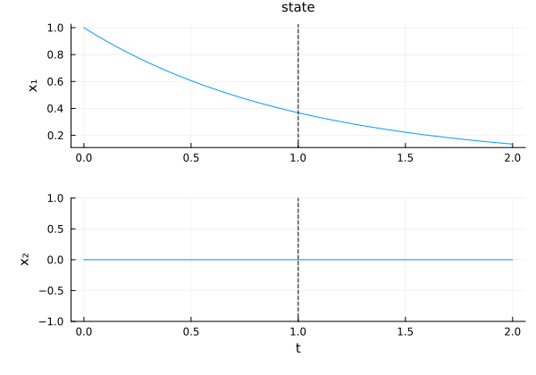
hsol = hmpf((0.0, 2.0), x0, p0)
plot(hsol)  # state and costate, across both phases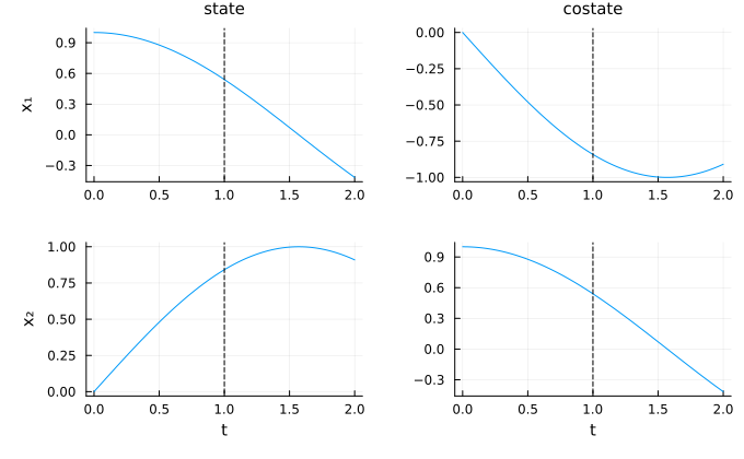
Switching lines and phase labels
The phase labels are written on the control panel, or on the first panel when there is no control. Four keywords control the switching structure on the plot:
| Keyword | Values (default first) | Effect |
|---|---|---|
switching_style | NamedTuple() / a NamedTuple / :none | style of the vertical lines at the switching times (dashed black lines by default); :none hides them |
phase_labels | :control / :all / :none | write the labels on the control panel (or the first panel), on every panel, or nowhere |
phase_labels_style | NamedTuple() | color, fontsize, halign, valign of the labels |
jumps | :segment / :none | draw a jump as a vertical segment, or break the curve between the two limits |
plot(sol_lab) # labels "decay" and "fast decay", state jump at t = 1.0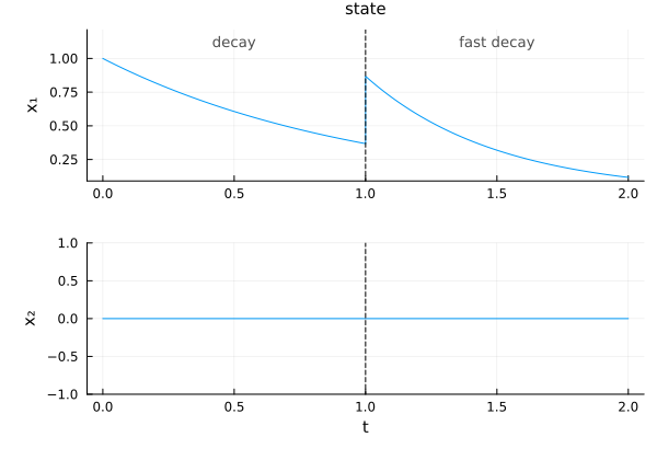
plot(sol_lab; switching_style=(color=:red,), phase_labels_style=(fontsize=12,))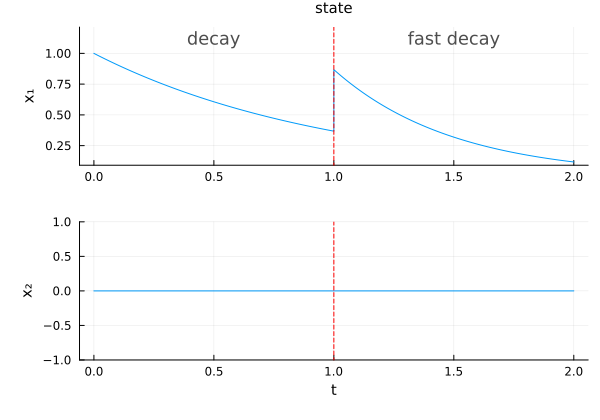
The vertical segment makes a jump easy to see, and to compare with a solution whose jump is smoothed (e.g. from a direct method); it does not mean that the trajectory takes the values in between. With jumps=:none, the curve stops at the left limit and starts again at the right limit:
plot(sol_lab; jumps=:none)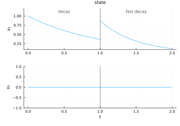
The limits are exact: the left limit is the end of the phase that finishes at the switching time, the right limit the start of the next phase, after the jump (x + Δx, p + Δp); the control on each side is given by the law of its phase at these values. They are not read from the next point of the time grid. The whole trajectory keeps one color: the phases are parts of the same curve, not separate series.
Different dynamics — kink at the switching time
When the two phases use different vector fields, the slope changes abruptly at the switching time. The trajectory is continuous but not differentiable:
# phase 1: f(x) = -x   |   phase 2: f(x) = -2x
sol_het = mpf_het((0.0, 2.0), x0)
plot(sol_het)   # kink visible at t = 1.0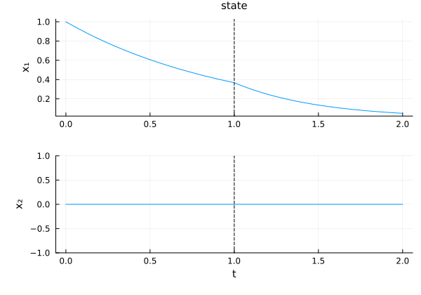
State jump — discontinuity in state
A non-zero additive jump x ← x + jump_x produces a visible discontinuity in the state trajectory:
# jump_x = [0.5, 0.0] defined above
sol_jump = mpf_jump((0.0, 2.0), x0)
plot(sol_jump)   # state jumps by [0.5, 0.0] at t = 1.0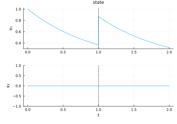
Hamiltonian flow — costate jump
For Hamiltonian flows, hflow1 * (t, jump_p, hflow2) adds an additive vector to the costate (p ← p + jump_p). The state remains continuous:
jump_p = [0.0, 0.5]
hmpf_jp = hflow1 * (1.0, jump_p, hflow2)
hsol_jp = hmpf_jp((0.0, 2.0), x0, p0)
plot(hsol_jp)   # costate jumps by [0.0, 0.5] at t = 1.0, state unchanged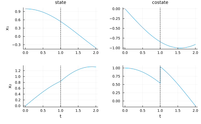
Hamiltonian flow — simultaneous state and costate jump
hflow1 * (t, jump_x, jump_p, hflow2) jumps both components at once (x ← x + jump_x, p ← p + jump_p):
jump_xx, jump_pp = [0.1, 0.0], [0.0, 0.5]
hmpf_jxp = hflow1 * (1.0, jump_xx, jump_pp, hflow2)
hsol_jxp = hmpf_jxp((0.0, 2.0), x0, p0)
plot(hsol_jxp)   # both state and costate jump at t = 1.0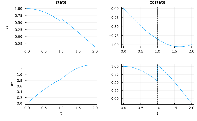
State function jump
A callable f(x) transforms the state at the switching time:
mpf_fn = flow1 * (1.0, x -> 2.0 .* x, flow2)
sol_fn = mpf_fn((0.0, 2.0), x0)
plot(sol_fn)   # state doubled at t = 1.0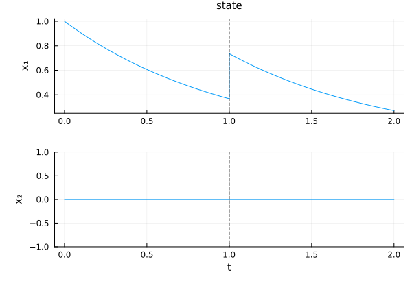
Hamiltonian function jump — full transformation
A callable f(x, p) transforms both components simultaneously:
hmpf_fn = hflow1 * (
    1.0, (x, p) -> (2.0 .* x, p .+ 0.5), hflow2
)
hsol_fn = hmpf_fn((0.0, 2.0), x0, p0)
plot(hsol_fn)   # state doubled, costate shifted at t = 1.0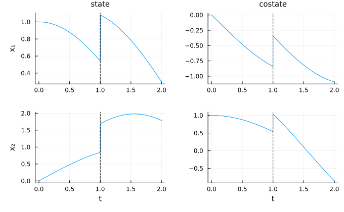
Hamiltonian state-only jump
Using nothing for the costate component leaves it unchanged:
hmpf_sx = hflow1 * (1.0, [0.1, 0.0], nothing, hflow2)
hsol_sx = hmpf_sx((0.0, 2.0), x0, p0)
plot(hsol_sx)   # state jumps, costate continuous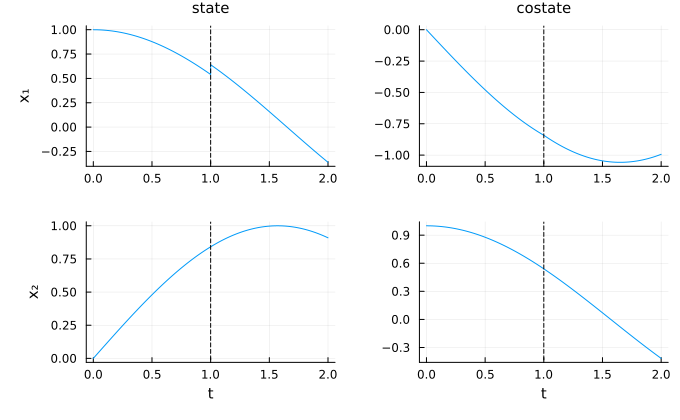
Design notes
Concatenation is an associative binary operation on flows:
(f1 * (t, f2)) * (s, f3).Phases may have different system and integrator types (
S,I): each phase can wrap a distinct function and use its own solver. Theflowsfield is a heterogeneous tuple, so the compiler specializes the integration loop per phase combination. The required uniformity across phases isTD,VD, and the dynamics family (state vs Hamiltonian), enforced at construction time.The trajectory integration merges phase results via
Integrators.merge, which keeps each phase's result and dense interpolant (a piecewise result): the merged trajectory is as accurate as a single-phase one. Withgrid=nothing, its time grid concatenates the phase grids, each switching time once; by default (no output grid at the call), an adaptive grid of 250 times is generated over the merged trajectory and every switching time appears once (the phases themselves are integrated without it). Evaluating at a switching time returns the end value of the phase that finishes there (before the jump);Trajectories.right_limitreturns the value after it. A grid of times given at the call is returned exactly (switching times are not added); a generated grid (grid=n,UniformGrid,AdaptiveGrid) has exactlyndistinct times, every switching time included once, the intervals being shared between the phases.
See also
CTFlows.MultiPhase.MultiPhaseStateFlow,CTFlows.MultiPhase.MultiPhaseHamiltonianFlow,CTFlows.MultiPhase.AnyMultiPhaseFlow— multi-phase flow types.CTFlows.MultiPhase.n_phases,CTFlows.MultiPhase.get_flow,CTFlows.MultiPhase.get_switching_time,CTFlows.MultiPhase.get_jump— phase accessors.CTFlows.MultiPhase.get_flows,CTFlows.MultiPhase.get_switching_times,CTFlows.MultiPhase.get_jumps,CTFlows.MultiPhase.get_labels— bulk accessors.CTFlows.Flows.label— the label of a flow.CTFlows.Trajectories.switching_times,CTFlows.Trajectories.phase_labels,CTFlows.Trajectories.left_limit,CTFlows.Trajectories.right_limit— the switching structure of a trajectory.